Process Details
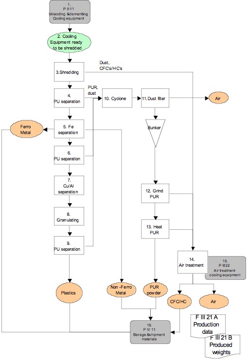
- The cooling equipment has been unloaded and dismantled according P III 11.
- The cooling equipment is ready to be shredded. Before the fridge can be shredded the fridge line needs to be turned on. Maintenance is responsible and instructions can be found in D III 21A.
- The production employee puts the cooling equipment on the conveyor belt leading it into the shredder. The cooling equipment is shredded.
- After shredding the cooling equipment now a material flow. Out of this flow first the PU foam is separated by suction.
- At this step iron pieces are taken out with a magnet.
- An extra step of PU separation follows.
- With an eddy current the non-ferrous ( cupper and aluminium) are separated from the plastics.
- The plastic are granulated again.
- An extra step of PU separation follows.
- The extracted PU foam goes trough a cyclone to take the big parts out.
- A dust filer follows to take the dust out.
- The dust and PU are colleted in a bunker. With a screw this fraction is let to a PU grinder.
- The grinded PU is heated afterwards to make it release more CFC’s.
- There is suction on the shredding, grinding and heating of PU to capture the release CFC’s into this airflow. This airflow is treated in order to take all CFCs out.
- In P III 22 this air treatment is describe in a more detailed. The production chief notes all the production results on form F III 21A. The production employee can give input for the produced weights true F III 21B.
- The result of these steps above is clean air and fractions of plastic, iron, non-ferrous, PU powder. These fractions will stored according to P IV 11.